BMC C-Series Engines
‘Big Log’ inlet manifold cylinder head modifications.
By Robert Greenfield
In 2014 I read an interesting article at Austin Rover Online about the C-series engine:
https://www.aronline.co.uk/engines/c-series/
There is an interesting bit about the 'dreaded' gallery inlet manifold on our saloon cars not being as bad as is often made out when compared to an Austin Healey 12-port head.
Comparing performance figures for 1961 the 6/110 engine makes 120bhp while the Austin-Healey 3000 makes 132bhp, with better torque for the 6/110 up to 3,500rpm. Very interesting is the fact that the 6/110 was confidentially detuned to 110bhp and the Healey 3000 saw several quick revisions to produce 150bhp!
The cylinder head studs going through the inlet gallery is not 'best practice' and seems to have been a fad at Morris Engines branch in the 1940s; the Wolseley 8 engine also has studs going through the inlet manifold. My thinking is that the mixture and cylinder filling of cylinders 1 and 6 must be compromised compared to cylinders 3 and 4 and the whole engine would have to be tuned slightly richer to compensate.
At the end of the article comment #3 (5 March 2012) got my attention:
"...There was a modification (from Derrington or Downton, I think) which used short bolts in the bottom of the gallery, accessed through larger holes in the top, which were then blanked off. This left the gallery almost unrestricted improving performance & economy."
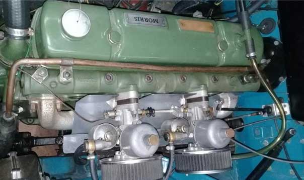
At the same time, I was sent some photos from Auckland of a heavily modified cylinder head that was taken off a Morris Isis. On this cylinder head, the inlet manifold had been machined off, leaving direct access to each cylinder's port. Each pair of inlet ports had a mounting for an SU carb, and presumably some sort of connection to the other 2 carbs with a balance pipe.
I'm told that the car went very well with the original 2.6litre engine block; he could burn rubber changing into 2nd gear!
I started a discussion that turned into 7 pages of chat on the Morris pages of the Wolseley Forum (www.wolseleyforum.com). Ivan found an old cylinder head and had a look at machining off the inlet manifold to see where problems may occur. He found one problem when he went through to the water jacket opposite cylinders 1 and 6 and this can be overcome next time this is attempted.
Machining off the inlet manifold is an interesting project and I hope someone gives this a go sometime. My choice was to investigate fitting short bolts at the bottom of the manifold to leave as much of the manifold unobstructed as possible. This would be a subtle modification, needing a trained eye to see any difference from a standard cylinder head when installed.
I had a chat to Ralph at Engine Rebuilders in New Plymouth and I was greatly heartened that he didn't think I was crackers for attempting this and that he remembered doing similar things to Ford engines.
I thought that a 'big-log' inlet manifold cylinder head from a 6/110 would be the best starting point because of better breathing potential, so I bought one from my branch of WCC (Manawatu). It turned out to be cracked, so it was sacrificed in the name of science and art; Ralph cut up a section of the cylinder head to see where the water jacket was I relation to the bottom of the manifold. We needed to know this because the bolt heads need a flat surface at the bottom of the manifold so each bolt can seat properly. For this, we needed to know how far down we could go to create a flat surface. It would also be an advantage to get the bolt head flush with the manifold if possible, so the bolt could be completely out of the path of the airflow.
I got another cylinder head from the parts shed (thanks Michael K!) and this one was good - no cracks. I got Ralph to give it a birthday - set up for unleaded, new valve guides, 3- angle cut on the valve seats and tidy the combustion chambers and ports if necessary. Now for the interesting bit...
Only the middle four-cylinder head studs are in the way of the fuel/air mixture; the two pairs of studs adjacent to cylinders 1 and 6 are not in the way, so they were left as-is.
The holes in the top of the inlet manifold for the middle four-cylinder head studs were enlarged and threaded for 3/8" hex-headed plugs. The bottom of the manifold was machined flat for four hex-headed 3/8" bolts.
The heads of the bolts protrude up into the inlet manifold by 10mm. It is possible that Ralph could have machined deeper holes, but neither of us wanted to risk going through to the water jacket and the inlet manifold is largely unobstructed... certainly better than before!
All bolts and nuts are torqued to standard rating - 75 lb-ft. Is it better? Good question! There are lots of variables that I am still working through. I fitted the cylinder head to my 2.6L Morris Isis in mid-2015. My goal was to get better fuel consumption due to a more even mixture going into each cylinder and hopefully more power!
When I first installed the new head the clutch slipped at full power when it was not slipping before, so perhaps more power, or perhaps the clutch was dodgy anyway.
I'm now getting 24mpg instead of 20-21mpg, but the car now has an overdrive gearbox and I've also recentred the SU jets.
There are still some things to iron out: the non-standard camshaft is an unknown and the tendency for the car to hold back sometimes on acceleration is something I have not sorted out yet. I think it would be a good idea to get the car onto a rolling road to see if the SU needles can be better selected (currently they are standard 6/90 High Compression needles).
I'm hoping that some other people want to give this a go. Perhaps the best time to do it is when the cylinder head is off already. The modification requires minimal invasive surgery and is difficult to see (if you wanted to have it look exactly right it would not be too difficult to attach a dummy washer, nut and small piece of a stud to the top of the hex plug. Another advantage is better clamping force due to the bolt pulling from the bottom of the manifold tube. The standard set up with the stud and a nut at the top will slightly compress the manifold tube, according to the engine workshop.
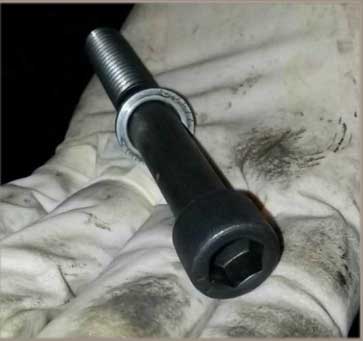
New studs (left) go inside inlet manifold; re-machined stud holes (right)


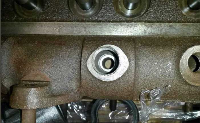
The finished project, with plugged manifold instead of studs passing all the way through.